Novastar Single Mode 10G Fiber Converter CVT10-S With 10 RJ45 Output For LED Display
.jpg)
.jpg)
.jpg)
.jpg)
.jpg)
.jpg)
.jpg)
Certifications
RoHS, FCC, CE, IC, RCM
Features
- Models include the CVT10-S (single-mode) and the CVT10-M (multi-mode).
- 2x optical ports with hot-swappable optical modules installed at the factory, bandwidth of each up to 10 Gbit/s
- 10x Gigabit Ethernet ports, bandwidth of each up to 1 Gbit/s
− Fiber in and Ethernet out
If the input device has 8 or 16 Ethernet ports, the first 8 Ethernet ports of the CVT10 are available.
If the input device has 10 or 20 Ethernet ports, all the 10 Ethernet ports of the CVT10 are available. If Ethernet ports 9 and 10 are found unavailable, they will be available after upgrading in the future.
− Ethernet in and fiber out
All the 10 Ethernet ports of the CVT10 are available.
- 1x type-B USB control port
Appearance
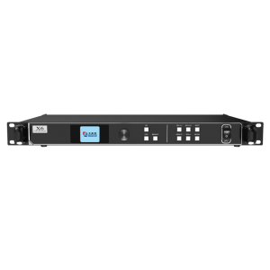
Front Panel


| Name | Description |
| USB | Type-B USB control port
Connect to the control computer (NovaLCT V5.4.0 or later) for upgrading the CVT10 program, not for cascading. |
| PWR | Power indicator
Always on: The power supply is normal. |
| STAT | Running indicator
Flashing: The device is functioning normally. |
| OPT1/OPT2 | Optical port indicators
Always on: The optical fiber connection is normal. |
| 1– 10 | Ethernet port indicators
Always on: The Ethernet cable connection is normal. |
| MODE | The button to switch the device working mode
The default mode is CVT mode. Only this mode is currently supported. |
| CVT/DIS | Working mode indicatorsAlways on: The corresponding mode is selected.
|
Rear Panel
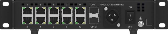
| Name | Description | |
| 100-240V~,
50/60Hz, 0.6A |
Power input connector
For the PowerCON connector, users are not allowed to plug in hot. Pour le connecteur PowerCON, les utilisateurs ne sont pas autorisés à se connecter à chaud. |
|
| OPT1/OPT2 | 10G optical ports | |
CVT10-S optical module description:
|
CVT10-S optical fiber selection:
|
|
CVT10-M optical module description:
|
CVT10-M optical fiber selection:
|
|
| 1– 10 | Gigabit Ethernet ports | |
Dimensions
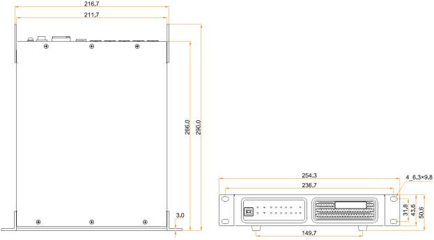
Tolerance: ±0.3 Unit: mm
Applications
The CVT10 is used for long-distance data transmission. Users can decide a connection method based on whether the sending card has optical ports.
The Sending Card Has Optical Ports

The Sending Card Has No Optical Ports

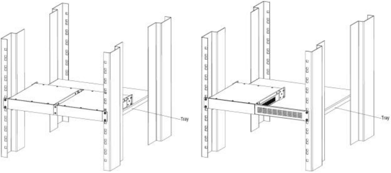
Assembling Effect Diagram
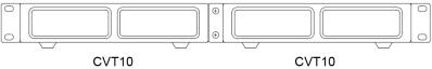
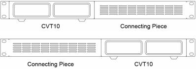
A single CVT10 device is half-1U in width. Two CVT10 devices, or one CVT10 device and a connecting piece can be combined into one assembly that is 1U in width.
Assembly of Two CVT10
Assembly of a CVT10 and a Connecting Piece
The connecting piece can be assembled to the right or left side of the CVT10.
Specifications
| Electrical Specifications | Power supply | 100-240V~, 50/60Hz, 0.6A |
| Rated power consumption | 22 W | |
| Operating Environment | Temperature | –20°C to +55°C |
| Humidity | 10% RH to 80% RH, non-condensing | |
| Storage Environment | Temperature | –20°C to +70°C |
| Humidity | 10% RH to 95% RH, non-condensing | |
| Physical Specifications | Dimensions | 254.3 mm × 50.6 mm × 290.0 mm |
| Net weight | 2.1 kg
Note: It is the weight of a single product only. |
|
| Gross weight | 3.1 kg
Note: It is the total weight of the product, accessories and packing materials packed according to the packing specifications |
|
| PackingInformation | Outer box | 387.0 mm × 173.0 mm × 359.0 mm, kraft paper box |
| Packing box | 362.0 mm × 141.0 mm × 331.0 mm, kraft paper box | |
| Accessories |
(without nuts)
|
The amount of power consumption may vary depending on factors such as product settings, usage, and environment.
Notes for Installation
Caution: The equipment must be installed in a restricted access location.
Attention: L'équipement doit être installé dans un endroit à accès restreint. When the product needs to be installed on the rack, 4 screws at least M5*12 should be used to fix it. The rack for installation shall bear at least 9kg weight.
- Elevated Operating Ambient - If installed in a closed or multi-unit rack assembly, the operating ambient temperature of the rack environment may be greater than room ambient. Therefore, consideration should be given to installing the equipment in an environment compatible with the maximum ambient temperature (Tma) specified by the manufacturer.
- Reduced Air Flow – Installation of the equipment in a rack should be such that the amount of air flow required for safe operation of the equipment is not compromised.
- Mechanical Loading – Mounting of the equipment in the rack should be such that a hazardous condition is not achieved due to uneven mechanical loading.
- Circuit Overloading – Consideration should be given to the connection of the equipment to the supply circuit and the effect that overloading of the circuits might have on overcurrent protection and supply wiring. Appropriate consideration of equipment nameplate ratings should be used when addressing this concern.
- Reliable Earthing – Reliable earthing of rack-mounted equipment should be maintained. Particular attention should be given to supply connections other than direct connections to the branch circuit (e.g. use of power strips).