
Colorlight E80 Receiving Card HUB75 Port For Stage Rental Outdoor LED Screen Module
.png)
.png)

Features
- Integrated HUB75 interface, more convenient with less cost
- Reduces the plug connectors and malfunction, lower failure rate
- Superior display quality: high refresh rate, high grayscale, and high brightness with the conventional chips
- Perfect performance under lower grayscale status
- Better detail processing: partial dark at row, reddish at low gray, shadow problems can be solved
- Supports high-precision pixel level calibration in the brightness and the chromaticity
- Supports conventional chips, PWM chips, Silan chips and lighting chips
- Supports up to 1/64 scan
- Supports any pumping point and any pumping row and pumping column and data group offset to realize various freeform
display, spherical display, creative display,etc.
- Supports 16 groups of RGB signal outputs
- Large loading capacity
Wide working voltage range with DC3.8V~5.5V
Compatible with all series of Colorlight sending devices
Specifications
| Control System Parameters | |
| Control Area | Conventional chips:128×512 pixels,PWM chips:256×512 pixels |
| Network Port Exchange | Support, arbitrary use |
| Synchronization | Nanosecond synchronization between cards |
| Display Effect | |
| Gray Level | Maximum 65536 levels |
| Minimum Unit of OEValues | 8ns, 8ns multiples steps |
| Gray Scale Compensation | Each level grayscale compensates separately |
| Display Module Compatibility | |
| Chip Supports | Supports conventional chips, PWM chips, Silan chips and other mainstream chips |
| Scan Type | Supports up to 1/64 scan |
| Module SpecificationsSupport | Supports 8192 pixels within any row,any column |
| Cable Direction | Supports route from left to right, from right to left, from top to bottom.from bottom to top. |
| Data group | 16 groups of RGB data |
| Data Folded | Supports 2~8 any discount |
| Data Exchange | 16 groups of dataforany exchange |
| Module Pumping Point | Supports any pumping point |
| Module Pumping Row,Pumping Column | Supports any pumping row and pumping column |
| Data Serial Transmission | Supports R1G1B1,R16G16B16,etc.in the form of serial |
| Compatible Device and Interface Type | |
| Communication Distance | Suggest CAT5ecable≤100m |
| Compatible withTransmission Equipment | Gigabit switch, fiber converter, optical switches |
| DC Power Interface | Wafer VH3.96mm-4P,Barrier Terminal Block-8.25mm-2P |
| HUB Interface Type | HUB75 |
| Physical Parameters | |
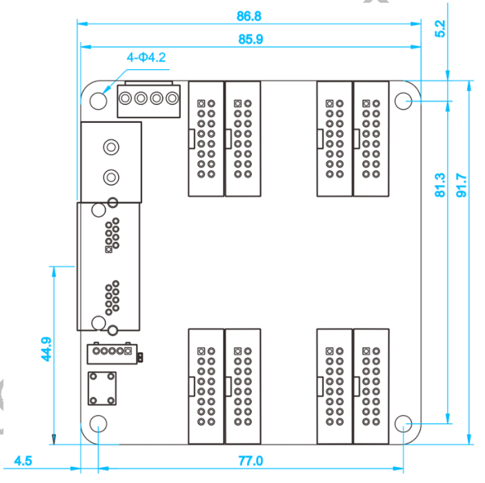
| Size | 86.8×91.7mm |
| Input voltage | DC3.8V~5.5V |
| Rated Current | 0.6A |
| Rated PowerConsumption | 3W |
| Storage and TransportTemperature | -40℃~125℃ |
| Operating Temperature | -25℃~75℃ |
| Body Static Resistance | 2KV |
| Weight | 64g |
| Pixel Level Calibration | |
| Brightness Calibration | Supported |
| Chromaticity Calibration | Supported |
| Other Features | |
| Redundant Backup | Supports loop backup and dual sender backup |
| Shaped Screen | Supports data group offset to realize various freeform display, spherical display, creative display,etc. |
Hardware
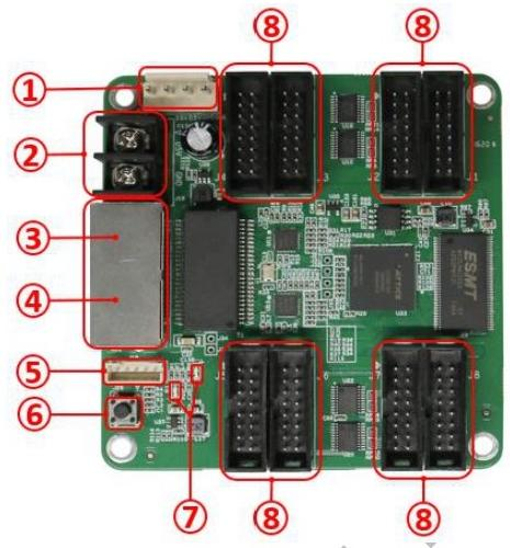
Interface
| S/N | Name | Function | Remarks | |
| 1 | Power 1 | Connect to DC 3.8V~5.5V power supply for the receiving card | Only one is used. | |
| 2 | Power 2 | Connect to DC 3.8V~5.5V power supply for the receiving card | ||
| 3 | Network port A | RJ45,for transmitting data signals | The dual network ports can achieve import/export at random, which can be identified
in an intelligent way by the system. |
|
| 4 | Network port B | RJ45,for transmitting data signals | ||
| 5 | External interface | For indicator light and test button | ||
| 6 | Test button |
The attached test procedures can achieve four kinds of monochrome display (red,green, blue and white),as well as horizontal, vertical and other display scan modes |
||
| 7 | Power indicator light | Red indicator light shows that the power supply is normal | D1 | |
| Signal indicator light | Flashes once per second | Receiving card: normal working Network cable connection: normal | D2 | |
| Flashes 10 times per second | Receiving card:normal workingCabinet:Sorting &Highlight | |||
| Flashes 4 times per second | Receiving card: backing up senders(loop backup status) | |||
| 8 | HUB pins | HUB75 Interface, J1~J8 connected to display modules | ||
Definitions of HUB75
| Data signal | Scanning signal | Control signal | |||||
| GD1 | GND | GD2 | E | B | D | LAT | GND |
| 2 | 4 | 6 | 8 | 10 | 12 | 14 | 16 |
| 1 | 3 | 5 | 7 | 9 | 11 | 13 | 15 |
| RD1 | BD1 | RD2 | BD2 | A | C | CLK | OE |
| Data signal | Scanning signal | Control signal | |||||
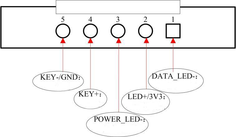
Definition of External Interface
Dimensions
Unit:mm
Tolerance: ±0.1 Unit: mm
Products categories
-
Colorlight C3 Pro LED Screen Multimedia Player ...
-
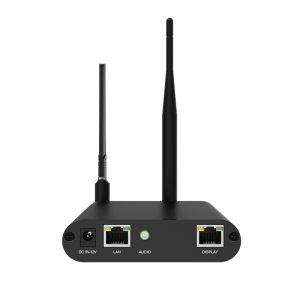
Colorlight A35 Media Player With 1 LAN Port For...
-
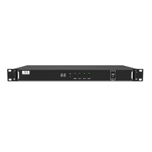
Colorlight X3 Video Processor Full Color LED Sc...
-
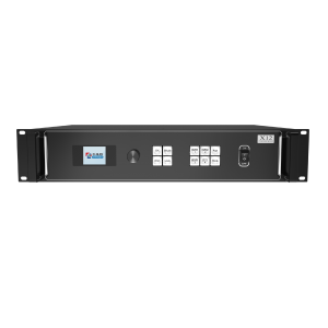
Colorlight X12 Video Processor Full Color LED D...
-
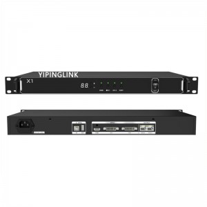
Colorlight X1 Video Processor Full Color LED Di...
-
Colorlight sending card S2 sender work with 5A-...


