Colorlight E120 Receiving Card With 12 HUB75 Ports For LED Display Indoor Small Spacing Module
.png)
.png)
.png)
Features
Display effect
- 8bit video source input.
- Color temperature adjustment.
- 240Hz frame rate.
- Better gray at low brightness.
Correction processing
• Pixel-to-pixel calibration in brightness and chromaticity.
Easy maintenance
- Highlight and OSD.
- Screen rotation.
- Data group offset.
- Any pump row and any pump column and any pump point.
- Quick firmware upgrade and quick release of correction coefficients.
Stable and reliable
- Loop redundancy.
- Ethernet cable status monitoring.
- Firmware program redundancy and readback.
- 7X24h uninterrupted work.
Feature details
| Display effect | |
| 8bit | 8bit color depth video source input and output, monochrome grayscale is 256, can be matched with 16777216 kinds of mixed colors. |
| Frame rate | Adaptive frame rate technology, not only supports 23.98/24/29.97/30/50/59.94/ 60Hz regular and non-integer frame rates, but also outputs and displays 120/240Hz high frame rate pictures, which greatly improves picture fluency and reduces drag film. (*it will affect the load). |
| Color temperature adjustment | Color temperature adjustment, that is, saturation adjustment, to enhance the expressiveness of the picture. |
| Better gray at low brightness | By optimizing the gamma meter algorithm, the display screen can maintain the integrity and perfect display of gray scale when reducing the brightness, showing the display effect of low brightness and high gray scale. |
| Calibration | 8bit precision brightness and chromaticity correction point by point, which can effectively eliminate the chromatic aberration of the lamp point, ensure the uniformity and consistency of the color brightness of the entire screen, and improve the overall display effect. |
| Shortcut operation | |
| Cabinet highlight | Using the control software, you can quickly mark the selected target cabinet, display a flashing box on the front of the cabinet, and change the flashing frequency of the cabinet indicator at the same time, which is convenient for front and rear maintenance. |
| Quick OSD | Using the control software, you can quickly mark the actual hardware connection serial number of the receiving card corresponding to the Ethernet port, which is convenient for setting the connection relationship of the screen. |
| Image rotation | Single cabinet image to be rotated at 9071807270° angles, and with part of the main control, the single cabinet image can be rotated and displayed at any angle. |
| Data group offset | Screen offset in units of data groups, suitable for simple special-shaped screens |
| Hardware monitoring | |
| Bit error detection | It supports the detection of data transmission quality and error code between receiving cards, and can easily and quickly identify the cabinet with abnormal hardware connection, which is convenient for maintenance. |
| Redundancy | |
| Loop redundancy | The redundant Ethernet port is used to increase the connection with the transmitting equipment and increase the reliability of cascading between equipment. When one circuit fails, it can realize seamless switching to the other circuit and ensure the normal display of the screen. |
| Firmware redundancy | It supports firmware program backup and can be upgraded safely. There is noneed to worry about the loss of firmware program due to cable disconnectionor power interruption during the upgrade process. |
Basic parameters
| Control System Parameters | |
| Control Area | Normal chips: 128X1024pixels, PWM chips: 192X1024 pixels, Shixin chips: 162X1024 pixels. |
| Ethernet Port Exchange | Supported, arbitrary use. |
| Display Module Compatibility | |
| Chip Support | Normal chips, PWM chips, Shixin chips. |
| Scan Type | Up to 1/128 scan. |
| Module Specifications
Supported |
Module of any row and column within 13312pixels. |
| Cable Direction | Route from left to right, from right to left, from top to bottom, from bottom to top. |
| Data Group | 24 groups of parallel RGB full color data and 32 groups of serial RGB data, which can be expanded to 128 groups of serial data, data groups can be exchanged freely. |
| Data Folded |
|
| Module pumping point, row and column | Any pumping point and any pumping row and any pumping column. |
| Monitoring Function | |
| Bit Error Monitoring | Monitor the total number of data packets and error packets to check network quality. |
| Pixel-to-Pixel Calibration | |
| Brightness Calibration | 8bit |
| Chromaticity Calibration | 8bit |
| Other features | |
| Redundancy | Loop redundancy and firmware redundancy. |
| Optional functions | Shaped screen. |
Hardware
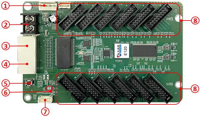
Interface
|
S/N |
Name |
Function |
|
| 1 |
Power 1 |
Connect to DC 3.8V-5.5V power supply for the receiving card, only use one of them. | |
| 2 |
Power 2 |
||
| 3 |
Network port A |
RJ45, for transmitting data signals, dual network ports can enter and exit at will, and the system will automatically identify. | |
| 4 |
Network port B |
||
| 5 |
Test button |
The attached test procedures can achieve four kinds of monochrome display (red, green, blue and white), as well as horizontal, vertical and other display scan modes. | |
| 6 |
Power indicator light DI |
Red indicator light shows that the power supply is normal. | |
|
Signal indicator D2 |
Flashes once per second | Receiving card: normal working, Ethernet cable connection: normal. | |
| Flashes 10 times per second | Receiving card: normal working, Cabinet: Highlight. | ||
| Flashes 4 times per second | Receiving card: back up sender cards (Loop redundancy status). | ||
| 7 |
External interface |
For indicator light and test button. | |
| 8 |
HUB pins |
HUB75 Interface, J1-J12 connected to display modules. | |
The product photos in this article are for reference only, and only the actual purchase shall prevail.
Equipment Specifications
| Physical specifications | |
| Hardware interface | HUB75 interfaces |
| Ethernet port transmission rate | 1Gb/s |
| CommunicationDistance | Recommended: CAT5e cable<100m |
| Compatible withTransmission
Equipment |
Gigabit switch, Gigabit fiber converter, Gigabit fiber switch |
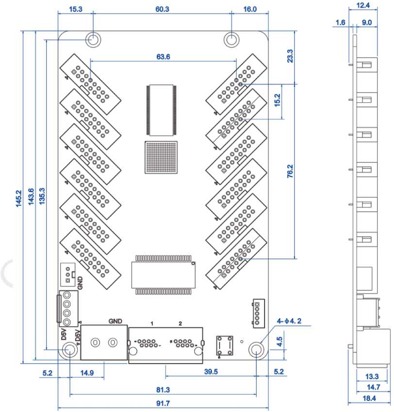
| Size | LXWXH/ 145.2mm(5.72") X 91.7mm(3.61") X 18.4mm(0.72") |
| Weight | 95g/0.21lbs |
| Electrical specification | |
| Voltage | DC3.8〜5.5V,0.6A |
| Rated power | 3.0W |
| Body Static Resistance | 2KV |
| Operating environment | |
| Temperature | -25°C〜75°C (-13°F~167°F) |
| Humidity | 0%RH-80%RH, no condensation |
| Storage environment | |
| Temperature | -40°C〜125°C (-40°F~257°F) |
| Humidity | 0%RH-90%RH, no condensation |
| Package information | |
| Packaging rules | Standard blister card tray device, 100 cards per carton |
| Package size | WXHXD/603.0mm(23.74")X501.0mm(7.48") X 190.0mm(19.72") |
| Certification |
| RoHS |
Definitions of HUB75
| Data signal | Scanning signal | Control signal | |||||
| GD1 | GND | GD2 | E | B | D | LAT | GND |
| 2 | 4 | 6 | 8 | 10 | 12 | 14 | 16 |
| 1 | 3 | 5 | 7 | 9 | 11 | 13 | 15 |
| RD1 | BD1 | RD2 | BD2 | A | C | CLK | OE |
| Data signal | Scanning signal | Control signal | |||||
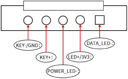
Definition of External Interface
Reference Dimensions
Unit:mm
Tolerance: ±0.1 Unit: mm
-300x300.png)