
Huidu B8L Professional LED Poster Screen Control System Special Control Card for LED Advertising Screen

.png)
Product Features
Input:
1. Support 1 Gigabit input network port to connect to the network, communicate with the outside world through TCP/UDP;
2. Support 2 HDMI1.4 input interface, support cascade splicing, picture-in-picture function;
3. Support 2 USB (USB 2.0 / USB 3.0), for USB disk program playback, firmware upgrade or capacity expansion, etc;
4. Support 1 OTG interface (customized OTG/USB mode, default USB disk function);
5. Support 1 TTL sensor interface, external each environment monitoring sensor or GPS, etc;
6. Support 1 RS232 and RS485 interface (center control docking);
7. Support 1 K0 relay interface.
Output:
1. Standard 2 Gigabit output network ports, Cascade with receiving card to realize display screen loading;
2. 1 HDMI OUT signal output, for cascading signal loop-out or screen monitoring;
3. 1 2PIN MIC interface, (reserved) for external audio equipment;
4. 1 TRS 3.5mm standard dual-channel audio output.
Function:
1. Single card supports 1,300,000 pixels; cascading supports 5,240,000 pixels with maximum width of 65,536 pixels or height of 8, 192 pixels; maximum cascading support of 14 units;
2. Supports third-party information publishing software (APP)
3. Supports local content editing, production and playback;
4. Multi-platform wireless screen mirroring compatible with Windows, iOS, Android and dedicated casting devices;
5. Dual Wi-Fi chips supporting 2.4G/5G bands, enabling high-resolution low-latency casting with simultaneous Wi-Fi hotspot and internet access;
6. Video playback capacity: 2×4K or 6×1080P or 10×720P or 20×360P streams;
7. Low-power standby mode with <0.5W power consumption;
8. 1×RS232 and 1×RS485 for central control integration.
Interface Description

| Number | Name | Description |
| 1 | Power seat | 4PIN 5V input interface. |
| 2 | FAN interface×2 | Reserved 2PIN fan connector |
| 3 | UART interface | Reserved UART interface |
| 4 | Wi-Fi AP interface×2 | Wi-Fi antenna connector for Wi-Fi/Bluetooth antenna connection |
| 5 | Wi-Fi STA interface×1 | Wi-Fi antenna connector for connecting Wi-Fi antenna |
|
6 |
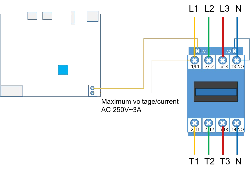
K0 Relay |
Relay on/off, supports maximum load: AC 250V~3A or DC 30V~3A.
Connection method is as follows: |
| 7 | IR Signal Receiver | Reserved infrared remote control signal receiving head, no infrared indicator light |
| 8 | USB 3.0 | USB 3.0, clip storage, program updates, firmware upgrades or capacity expansion |
| 9 | NEXT button | Reserved keys, default program switching function, software can be set to screen test function |
| 10 | ASYNC button | Reserve key for switching between asynchronous and synchronous modes
Lamp does not light up: current signal source is not in ASYNC mode Green light always on: Asynchronous playback |
|
11 |
HDMI input |
Reserve source switching button
No light: current source is not HDMI IN mode Green light is always on: synchronization mode, detect input source normal Green light blinking: synchronization mode, detecting abnormal input source |
|
12 |
HDMI LOOP |
Reserve source switching button
Lamp does not light: the current source is not HDMI LOOP mode Green light is always on: synchronization mode, detect the input source is normal Green light blinking: synchronization mode, detecting abnormal input source |
|
13 |
4G/5G Indicator |
Reservation Indicator
Red blinking: SIM card not detected Red light is always on: SIM card owes money or has no signal Yellow light is always on: mobile network is normal, not connected to the cloud server Green light is always on: mobile network is normal and connected to the cloud server. |
|
14 |
Wi-Fi STA indicator |
Reservation Indicator
Red light is always on: STA mode is on, not connected to the router. Yellow light is always on: the bridge is connected to the router, but not connected to the cloud server. Green light is always on: the bridge is connected to the router and the cloud server is connected. Red light is blinking or not on: STA mode is abnormal |
|
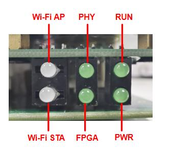
15 |
Wi-FiAP indicator |
Reservation Indicator
Lamp does not light: AP mode is not turned on or abnormal Green light flashing: AP mode is normal Red blinking: AP mode abnormal |
|
16 |
RUN indicator |
Reserved System Indicator
Blinking green: Operating system is running normally Long green light or no light: abnormal operation of the operating system |
|
17 |
Indicator board |
Front device indicator board
PWR indicator: green light is always on, power input is normal RUN indicator: green light flashing, the system is running normally, refer to serial number 16 for instructions PHY Indicator: reserved indicator light FPGA indicator: green blinking, the system is running normally Wi-FiAP indicator: refer to serial number 15 for description. Wi-Fi STA indicator: refer to serial number 14 for description. |
| 18 | HDMI OUT interface | HDMI1.4b output interface, for cascading data loop-out or screen monitoring |
|
19 |
HDMI LOOP interface |
HDMI 1.4 interface, synchronized signal input or splice input interface
Maximum resolution 2048×1152@60Hz Minimum resolution 800×600@60Hz Support customized resolution |
|
20 |
HDMI IN interface |
HDMI 1.4 interface, support adaptive scaling
Recommended resolution 1920×1080@60Hz Maximum resolution 3840×2160@30Hz Minimum resolution 800×600@60Hz Support customized resolution, support HDCP 1.4 |
|
21 |
OTG interface |
USB 3.0 used for material storage, program updates, firmware upgrades or capacity expansion (default USB flash drive function, factory configurable) |
| 22 | USB interface | USB2.0, used for material storage, updating programs, insert programs or expanding capacity. |
| 23 | TRS audio output | TRS 3.5mm standard dual-channel audio output port. |
| 24 | Iutput network port | Gigabit Ethernet port for communication with the outside world via TCP/UDP |
| 25 | Output network port×2 | 2 RJ45 output network port, cascade HD receiver card display |
|
26 |
PCIE-4G/5G seat | 4G/5G module holder (optional function, installed with 4G/5G antenna by default). |
|
27 |
RECOVERY interface |
Restore the factory button in the audio port, the device is powered on at the same time using a thin object (toothpick) through the AUDIO audio port against the inside of the RECOVERY button for 20 seconds and then release it, to enter the restoration of factory settings |
| 28 | TTL interface | Connection of TTL protocol external sensor accessories, such as environmental monitoring, multi-function sensors, etc. (optional device) |
| 29 | RS485 interface |
RS485 interface, connect RS485 protocol brightness, temperature and humidity and other sensors, as well as connecting other peripherals to achieve the corresponding function |
| 30 | RS232 interface |
RS232 interface, connect RS232 protocol brightness, temperature and humidity and other sensors, as well as connecting other peripherals to achieve the corresponding function |
| 31 | DEBUG interface | Prepared debugging interface |
| 32 | MIC interface | Differential MIC audio input reserved |
Product Size

Product Specifications
| Electrical parameters | Input power | DC 5V (5V 6A) |
| Maximum power consumption | 21W | |
| Storage | Running memory | 4GB |
| Internal storage | 64GB | |
| Storage environment | Temperature | -40℃ ~ 80℃ |
| Humidity | 0%RH~80%RH (No condensation) | |
|
Work environment |
Temperature | -40℃ ~ 70℃ |
| Humidity | 0%RH~80%RH (No condensation) | |
|
Packaging information |
List:
. 1 × B8L; . 1 × HDMI Cable; . 3 ×WiFi Antenna; . 1 ×Certificate of conformity; |
|
| Size | 189.86mm×137.92mm×24.80mm | |
| Net weight | 0.60KG ( ±10g) | |
|
Protection level |
IP20
Please pay attention to waterproofing, such as preventing water from dripping into the product, and do not get the product wet or rinse it |
|
|
System software |
Android 11.0 operating system software
Android terminal application software FPGA software |
|
Poster Screen Application
1. Display independently:Each display screen is independent and plays independently without interfering with each other.

2. Spliced display: With HDMI high-definition cable connected to put the contents of multiple display screens into a whole picture.

3. Creative display: supports 360° free splicing of multiple displays with different resolutions in any direction.

4. Multi-screen synchronization display: Multiple independent displays synchronously display the same image at the same time.

Description:
1. The B8L LED Poster Screen Specialized Control System product package in the application scenario diagram is detailed in the packing list.
2. The optional equipment not included in the scene diagram needs to be purchased in a separate order, if you have any questions, please contact our business colleagues to deal with.
Communication Methods
1. Stand-alone control, supports Wi-Fi, network port direct connection, and USB interface for communication.

2. Cluster control, support Internet remote control.

3. Synchronous control, synchronous playback via HDMI signal input.

System Supporting Software
| Name | Type | Description |
|
HDPlayer |
PC |
Local display screen management system, used for configuring, program editing, program publishing, etc. |
|
Xiaohui Cloud |
Web |
Cloud display information release system, log in through the browser, realize LED display remote cluster management and information release functions |
|
LEDArt |
Mobile APP | Supports Android, IOS, and Harmony platforms to realize the control of LED display screens and wireless program publishing. |
Attachment: Product Appearance
1.png)

Products categories
-
-300x300.jpg)
Huidu LED Controller VP820A Two in One Video Pr...
-

Huidu LED Controller A7 Multimedia Player with ...
-

Huidu VP410A VP410C LED Video Processor Controller
-
-300x300.jpg)
Huidu C16L can Load 200,000 pixels Full Color L...
-

Huidu HDP601 Synchronous Single Window LED Vide...
-

Huidu B6L LED Poster LED Display Control System...


