
Novastar VX1000 Video Processor With 10 LAN Ports For Rental LED Video Wall


Introduction
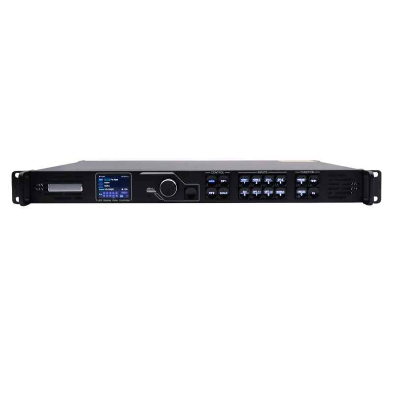
The VX1000 is NovaStar's new all-in-one controller that integrates video processing and video control into one box. It features 10 Ethernet ports and supports video controller, fiber converter and Bypass working modes. A VX1000 unit can drive up to 6.5 million pixels, with the maximum output width and height up to 10,240 pixels and 8192 pixels, respectively, which is ideal for ultra-wide and ultra-high LED screen applications.
The VX1000 is capable of receiving a variety of video signals and processing high-resolution 4K×1K@60Hz images. In addition, the device features stepless output scaling, low latency, 3D, pixel-level brightness and chroma calibration and more, to present you with an excellent image display experience.
What's more, the VX1000 can work with NovaStar's supreme software NovaLCT and V-Can to greatly facilitate your in-field operations and control, such as screen configuration, Ethernet port backup settings, layer management, preset management and firmware update.
Thanks to its powerful video processing and sending capabilities and other outstanding features, the VX1000 can be widely used in applications such as medium and high-end rental, stage control systems and fine-pitch LED screens.
Certifications
CE, UL&CUL, IC, FCC, EAC, UKCA, KC, RCM, CB, RoHS, NOM
Features
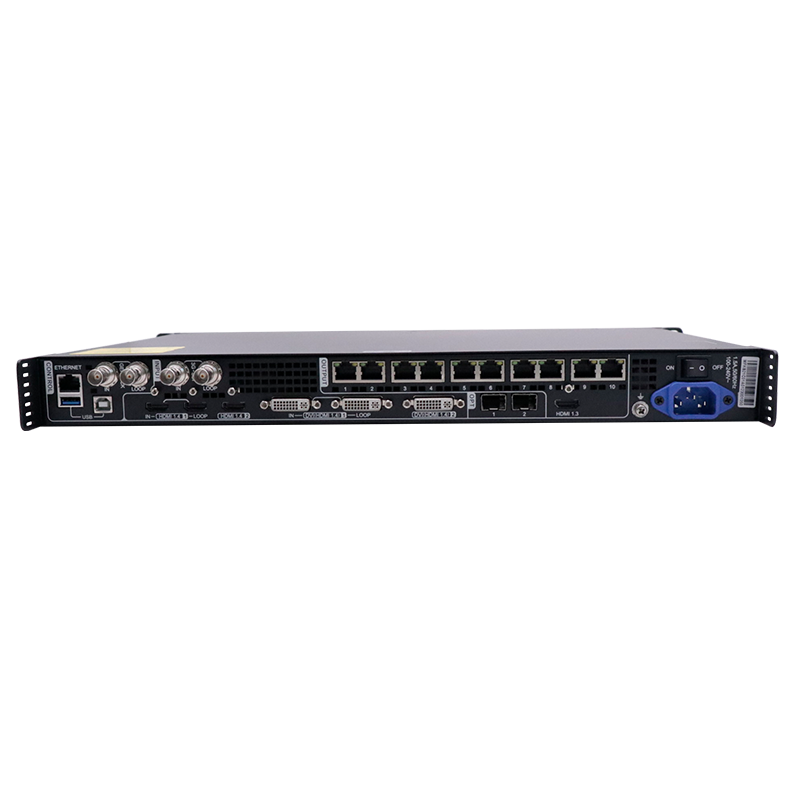
⬤ Input connectors
− 1x HDMI 1.3 (IN & LOOP)
− 1x HDMI 1.3
− 1x DVI (IN & LOOP)
− 1x 3G-SDI (IN & LOOP)
− 1x 10G optical fiber port (OPT1)
⬤Output connectors
− 6x Gigabit Ethernet ports
A single device unit drives up to 3.9 million pixels, with a maximum width of 10,240 pixels and a maximum height of 8192 pixels.
− 2x Fiber outputs
OPT 1 copies the output on 6 Ethernet ports.
OPT 2 copies or backs up the output on 6 Ethernet ports.
− 1x HDMI 1.3
For monitoring or video output
⬤ Self-adaptive OPT 1 for either video input or sending card output
Thanks to the self-adaptive design, OPT 1 can be used as either an input or output connector, depending on its connected device.
⬤ Audio input and output
− Audio input accompanied with HDMI input source
− Audio output via a multifunction card
− Output volume adjustment supported
⬤ Low latency
Reduce the delay from the input to receiving card to 20 lines when the low latency function and Bypass mode are both enabled.
⬤ 3x layers
− Adjustable layer size and position
− Adjustable layer priority
⬤ Output synchronization
An internal input source or external Genlock can be used as the sync source to ensure the output images of all cascaded units in sync.
⬤ Powerful video processing
− Based on SuperView III image quality processing technologies to provide stepless output scaling
− One-click full screen display
− Free input cropping
⬤ Easy preset saving and loading
− Up to 10 user-defined presets supported
− Load a preset by simply pressing one button
⬤ Multiple kinds of hot backup
− Backup between devices
− Backup between Ethernet ports
− Backup between input sources
⬤ Mosaic input source supported
The mosaic source is composed of two sources (2K×1K@60Hz) accessed to the OPT 1.
⬤ Up to 4 units cascaded for image mosaic
⬤ Three working modes
− Video Controller
− Fiber Converter
− Bypass
⬤ All-round color adjustment
Input source and LED screen color adjustment supported, including brightness, contrast, saturation, hue and Gamma
⬤ Pixel level brightness and chroma calibration
Work with NovaLCT and NovaStar calibration software to support brightness and chroma calibration on each LED, effectively removing color discrepancies and greatly improving LED display brightness and chroma consistency, allowing for better image quality.
⬤ Multiple operation modes
Control the device as you wish via V-Can, NovaLCT or device front panel knob and buttons.
Appearance
Front Panel
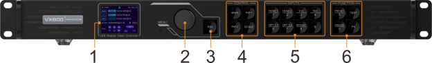
| No. | Area | Function | |
| 1 | LCD screen | Display the device status, menus, submenus and messages. | |
| 2 | Knob | Rotate the knob to select a menu item or adjust the Press the knob to confirm the setting or operation. | parameter value. |
| 3 | ESC button | Exit the current menu or cancel an operation. | |
| 4 | Control area | Open or close a layer (main layer and PIP layers), and show the layer status.Status LEDs:
− On (blue): The layer is opened. − Flashing (blue): The layer is being edited. − On (white): The layer is closed. SCALE: A shortcut button for the full screen function. Press the button to make the layer of the lowest priority fill the entire screen. Status LEDs: − On (blue): Full screen scaling is turned on. − On (white): Full screen scaling is turned off. |
|
| 5 | Input sourcebuttons | Show the input source status and switch the layer input source.Status LEDs:
On (blue): An input source is accessed. Flashing (blue): The input source is not accessed but used by the layer. On (white): The input source is not accessed or the input source is abnormal.
When a 4K video source is connected to OPT 1, OPT 1-1 has a signal but OPT 1-2 does not have a signal. When two 2K video sources are connected to OPT 1, OPT 1-1 and OPT 1-2 both have a 2K signal. |
|
| 6 | Shortcut functionbuttons | PRESET: Access the preset settings menu. TEST: Access the test pattern menu.
Freeze: Freeze the output image. FN: A customizable button |
|
Note:
Hold down the knob and ESC button simultaneously for 3s or longer to lock or unlock the front panel buttons.
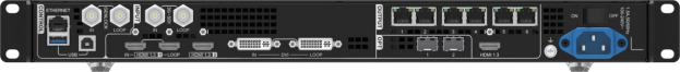
Rear Panel
| Connector | ||
| 3G-SDI | ||
| 2 | Max. input resolution: 1920×1200@60Hz HDCP 1.4 compliant
Interlaced signal inputs supported Custom resolutions supported − Max. width: 3840 (3840×648@60Hz) − Max. height: 2784 (800×2784@60Hz) − Forced inputs supported: 600×3840@60Hz Loop output supported on HDMI 1.3-1 |
|
| DVI | 1 | Max. input resolution: 1920×1200@60Hz HDCP 1.4 compliant
Interlaced signal inputs supported Custom resolutions supported − Max. width: 3840 (3840×648@60Hz) − Max. height: 2784 (800×2784@60Hz) − Forced inputs supported: 600×3840@60Hz Loop output supported on DVI 1 |
| Output Connectors | ||
| Connector | Qty | Description |
| Ethernet ports | 6 | Gigabit Ethernet ports Max. loading capacity: 3.9 million pixels
Max. width: 10,240 pixels Max. height: 8192 pixels Ethernet ports 1 and 2 support audio output. When you use a multifunction card to parse the audio, be sure to connect the card to Ethernet port 1 or 2. Status LEDs: The top left one indicates the connection status. − On: The port is well connected. − Flashing: The port is not well connected, such as loose connection. − Off: The port is not connected. The top right one indicates the communication status. − On: The Ethernet cable is short-circuited. − Flashing: The communication is good and data is being transmitted. − Off: No data transmission |
| HDMI 1.3 | 1 | Support monitor and video output modes. The output resolution is adjustable. |
| Optical Fiber Ports | ||
| Connector | Qty | Description |
| OPT | 2 | OPT 1: Self-adaptive, either for video input or for output− When the device is connected with a fiber converter, the port is used as an
output connector. − When the device is connected with a video processor, the port is used as an input connector. − Max. capacity: 1x 4K×1K@60Hz or 2x 2K×1K@60Hz video inputs OPT 2: For output only, with copy and backup modes OPT 2 copies or backs up the output on 6 Ethernet ports. |
| Control Connectors | ||
| Connector | Qty | Description |
| ETHERNET | 1 | Connect to the control PC or router.Status LEDs:
The top left one indicates the connection status. − On: The port is well connected. − Flashing: The port is not well connected, such as loose connection. − Off: The port is not connected. The top right one indicates the communication status. − On: The Ethernet cable is short-circuited. − Flashing: The communication is good and data is being transmitted. − Off: No data transmission |
| USB | 2 | USB 2.0 (Type-B):− Connect to the control PC.
− Input connector for device cascading USB 2.0 (Type-A): Output connector for device cascading |
| GENLOCKIN LOOP | 1 | Connect to an external sync signal. IN: Accept the sync signal.
LOOP: Loop the sync signal. |
Note:
Only the main layer can use the mosaic source. When the main layer uses the mosaic source, PIP 1 and 2 cannot be opened.
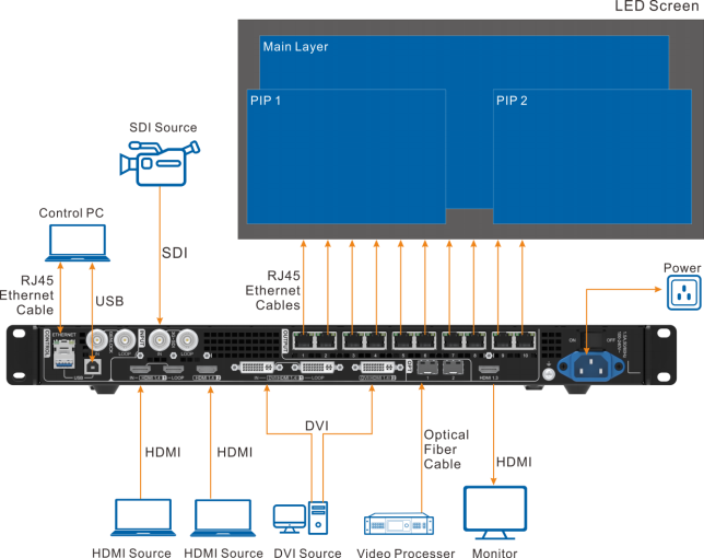
Applications
Specifications
| ElectricalParameters | Power connector | 100–240V~, 1.5A, 50/60Hz | |
| Rated powerconsumption | 28 W | ||
| OperatingEnvironment | Temperature | 0°C to 45°C | |
| Humidity | 20% RH to 90% RH, non-condensing | ||
| StorageEnvironment | Temperature | –20°C to +70°C | |
| Humidity | 10% RH to 95% RH, non-condensing | ||
| Physical Specifications | Dimensions | 483.6 mm × 351.2 mm × 50.1 mm | |
| Net weight | 4 kg | ||
| PackingInformation | Accessories | Flight Case | Carton |
| 1x Power cord1x HDMI to DVI cable
1x USB cable 1x Ethernet cable 1x HDMI cable 1x Quick Start Guide 1x Certificate of Approval 1x DAC cable |
1x Power cord1x HDMI to DVI cable
1x USB cable 1x Ethernet cable 1x HDMI cable 1x Quick Start Guide 1x Certificate of Approval 1x Safety Manual 1x Customer Letter |
||
| Packing size | 521.0 mm × 102.0 mm × 517.0 mm | 565.0 mm × 175.0 mm × 450.0 mm | |
| Gross weight | 10.4 kg | 6.8 kg | |
| Noise Level (typical at 25°C/77°F) | 45 dB (A) | ||
Video Source Features
| Input Connectors | Bit Depth | Max. Input Resolution | |
| HDMI 1.3 DVI
OPT 1 |
8-bit | RGB 4:4:4 | 1920×1200@60Hz (Standard)3840×648@60Hz (Custom)
600×3840@60Hz (Forced) |
| YCbCr 4:4:4 | |||
| YCbCr 4:2:2 | |||
| YCbCr 4:2:0 | Not supported | ||
| 10-bit | Not supported | ||
| 12-bit | Not supported | ||
| 3G-SDI | Max. input resolution: 1920×1080@60Hz DOES NOT support input resolution and bit depth settings.
Supports ST-424 (3G), ST-292 (HD) and ST-259 (SD) standard video inputs. |
||
Can we make any size we want? And what's the best size of led screen?
A: Yes, we can design any size according to your size requirement. Normally, advertising, stage led screen, The best aspect ratio of LED display are W16:H9 or W4:H3
What's the function of video processor?
A: It can make LED display more clear
B: It can have more input source to switch different signal easily, like different PC or camera.
C:It can scale the PC resolution into bigger or smaller LED display to display full image.
D: It can have some special function, like frozen image or text overlay, etc.
What's the difference between back service and front service led screen ?
A: Back service, that mean need enough space behind of the led screen, so that worker can do the installation or maintenance.
Front service, worker can do installation and maintenance from front directly. very convenience, and save space. especially is that led screen will fixed on the wall.
Can I have a sample order for LED products?
A: Yes, we welcome sample order to test and check quality.
What about the lead time?
A: We always have stock. 1-3 days can deliver cargo.
How do you ship the goods and how long does it take to arrive?
A: By express, sea, air, train
How to proceed an order for LED products?
A: Firstly, let us know your requirements or application.
Secondly, we quote according to your requirements or our suggestions.
Thirdly, customer confirms the design document and places deposit for formal order.
Fourthly, we arrange the production.
Is it OK to print my logo on the products?
A: Yes. Please inform us formally before our production and confirm the design firstly based on our sample.
What is the MOQ?
A: 1 piece is supported, Welcome you contact us for quotation.
What is the payment item?
A: The 30% deposit before production, balance payment 70% before delivery.
LED Display 6 Key Technologies
LED electronic display has good pixels, no matter day or night, sunny or rainy days, LED display can let the audience see the content, to meet people's demand for display system.
Image acquisition technology
The main principle of LED electronic display is to convert digital signals into image signals and present them through the luminous system. The traditional method is to use video capture card combined with VGA card to achieve display function. The main function of video acquisition card is to capture video images, and obtain the index addresses of line frequency, field frequency and pixel points by VGA, and obtain digital signals mainly by copying the color lookup table. Generally, software can be used for real-time replication or hardware theft, compared with hardware theft is more efficient. However, the traditional method has the problem of compatibility with VGA, which leads to blurred edges, poor image quality and so on, and finally damages the image quality of electronic display.
Based on this, industry experts developed a dedicated video card JMC-LED, the principle of the card is based on PCI bus using 64-bit graphics accelerator to promote VGA and video functions into one, and to achieve the video data and VGA data to form a superposition effect, the previous compatibility problems have been effectively solved. Secondly, the resolution acquisition adopts the full-screen mode to ensure the full Angle optimization of the video image, the edge part is no longer fuzzy, and the image can be arbitrarily scaled and moved to meet different playback requirements. Finally, the three colors of red, green and blue can be effectively separated to meet the requirements of true color electronic display screen.
Real image color reproduction
The principle of the LED full-color display is similar to that of the television in terms of visual performance. Through the effective combination of red, green and blue colors, different colors of the image can be restored and reproduced. The purity of the three colors red, green and blue will directly affect the reproduction of the image color. It should be noted that the reproduction of the image is not a random combination of red, green and blue colors, but a certain premise is required.
First, the light intensity ratio of red, green and blue should be close to 3:6:1; Secondly, compared with the other two colors, people have a certain sensitivity to red in vision, so it is necessary to evenly distribute red in the display space. Thirdly, because people's vision is responding to the nonlinear curve of the light intensity of red, green and blue, it is necessary to correct the light emitted from the inside of the TV by white light with different light intensity. Fourth, different people have different color resolution abilities under different circumstances, so it is necessary to find out the objective indicators of color reproduction, which are generally as follows:
(1) The wavelengths of red, green and blue were 660nm, 525nm and 470nm;
(2) The use of 4 tube unit with white light is better (more than 4 tubes can also, mainly depends on the light intensity);
(3) The gray level of the three primary colors is 256;
(4) Nonlinear correction must be adopted to process LED pixels.
The red, green and blue light distribution control system can be realized by the hardware system or by the corresponding playback system software.
Products categories
-

Huidu T16 4K Synchronous Sending Box with 8.84 ...
-
Linsn L3 Asynchronous LED Display Sender Box Me...
-

Huidu U6A Single/Dual-Color USB LED Control Car...
-
Novastar H2 H5 H9 H15 Video Splicing Processor ...
-

Novastar H15 Video Wall Splicing Processor for ...
-
Novastar TCC70A Offline Controller Sender and R...


