
Colorlight E320 Receiving Card With HUB75 Port For Soft Flexible LED Display Screen Modules
.png)
.png)
Specifications
| Control System Parameters | |
| Control area of every card | Conventional:128×1024pixels, PWM:256×1024 pixels |
| Network port exchange | Supported, arbitrary use |
| Gray level | Maximum 65536 levels |
| Display Module Compatibility | |
| Chip supports | Supports conventional chips, PWM chips and other mainstream chips |
| Scan mode | Two scanning methods to support refresh rate multiplier |
| Scan type | Supports any scan mode from static to 64 scans |
| Module Specifications | Support 8192 pixels within any row, any column |
| The direction of the cable | Supports route from left to right,from right to left, from top to bottom, from bottom to top. |
| Data Groups | 32 sets of parallel RGB full color data, 32 sets of serial RGB data |
| Data folded | Supports 1~8 any discount to improve refresh rate |
| Data exchange | 32 data groups for any exchange |
| Module snapshot | Supports any pumping point |
| Interface Type and Physical Parameters | |
| Communication distance | SuggestCAT5e cable≤100m |
| Compatible withtransmission equipment | Gigabit switch, fiber converter, optical switches |
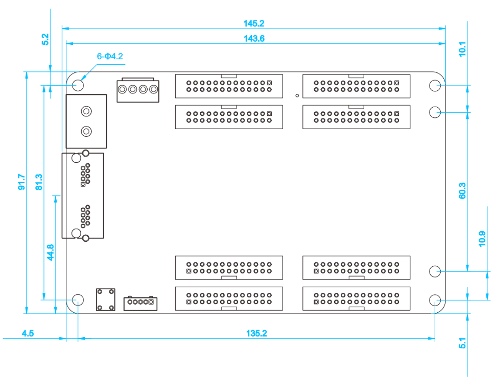
| Size | 145.2mm×91.7mm |
| Input voltage | DC3.8V~5.5V |
| Rated current | 0.6A |
| Rated power consumption | 3W |
| Storage and transport temperature | -40℃~125℃ |
| Operating Temperature | -25℃~75℃ |
| Body static resistance | 2KV |
| Weight | 94g |
| Pixel level Calibration | |
| Brightness Calibration | Supported |
| Chromaticity Calibration | Supported |
| Other Features | |
| Hot backup | Supports loop backup, double sending card backup and seamless switching |
| Shaped screen | Supports various free-form display, spherical display,creative display, etc.through the data arbitrary offset |
Hardware
Interface
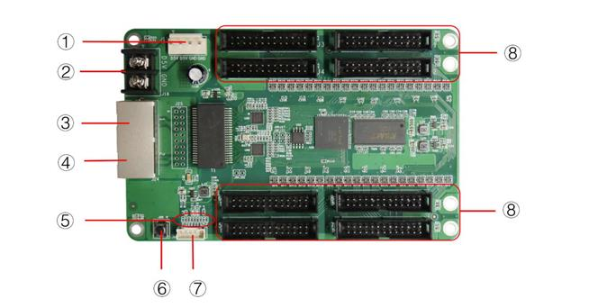
| S/N | Name | Function | Remarks |
| 1 | Power 1 | Connect DC 3.8~5.5V power supply for the receiving card | Only one is used. |
| 2 | Power 2 | Connect DC 3.8~5.5V power supply for the receiving card | |
| 3 | Network port A | RJ45,for transmitting data signals | The dual network ports can achieve import/export at random, which can be identified in an intelligent way by the system |
| 4 | Network port B | RJ45,for transmitting data signals | |
| 5 | Power/Signalindicator light | D1: power indicator lightD2:signal indicator light | Red light: powerGreen light:signal |
| 6 | Test button | The attached test procedures can achieve four kinds of monochrome display
(red green, blue and white),as well as horizontal, vertical and other display scan modes. |
|
| 7 | External interfaces | For indicator light and test button | |
| 8 | HUB pins | HUB75 Interface,J1~J8 connected to display modules |
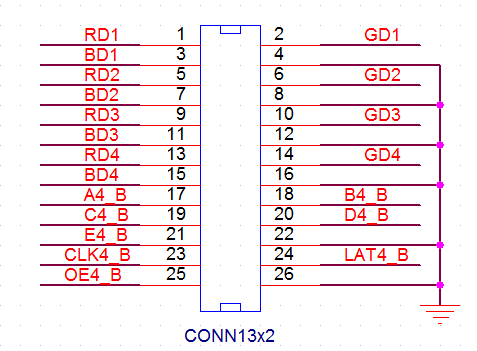
Definitions of HUB75
| Instructions | Definition | Pin No. | Definition | Instructions | |
|
Data signal
|
RD1 | 1 | 2 | GD1 | Data signal |
| BD1 | 3 | 4 | GND | Ground connection | |
| RD2 | 5 | 6 | GD2 | Data signal | |
| BD2 | 7 | 8 | GND | Ground connection | |
| RD3 | 9 | 10 | GD3 | Data signal | |
| BD3 | 11 | 12 | GND | Ground connection | |
| RD4 | 13 | 14 | GD4 | Data signal | |
| BD4 | 15 | 16 | GND | Ground connection | |
|
Row decoding signal
|
A4_B | 17 | 18 | B4_B | Row decoding signal |
| C4_B | 19 | 20 | D4_B | ||
| E4_B | 21 | 22 | GND | Ground connection | |
| Serial clock | CLK4_B | 23 | 24 | LAT4_B | Signal lock |
| Display enable | OE4_B | 25 | 26 | GND | Ground connection |
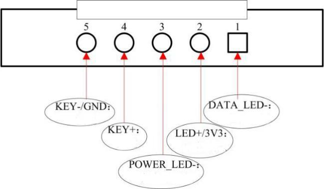
Definition of External Interface
Dimensions
Unit:mm
Tolerance: ±0.1 Unit: mm
Products categories
-
Colorlight S4 sending box card hdmi dvi input 4...
-
Colorlight C3 Pro LED Screen Multimedia Player ...
-
Colorlight X2s Video Processor Full Color LED D...
-
Colorlight X7 Video Processor Full Color LED Di...
-

Colorlight AX08 AI Media Station with 8 Gigabit...
-

Colorlight VX6 LED Video Processor with 3.93 Mi...


