
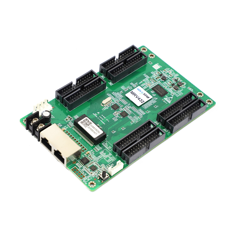
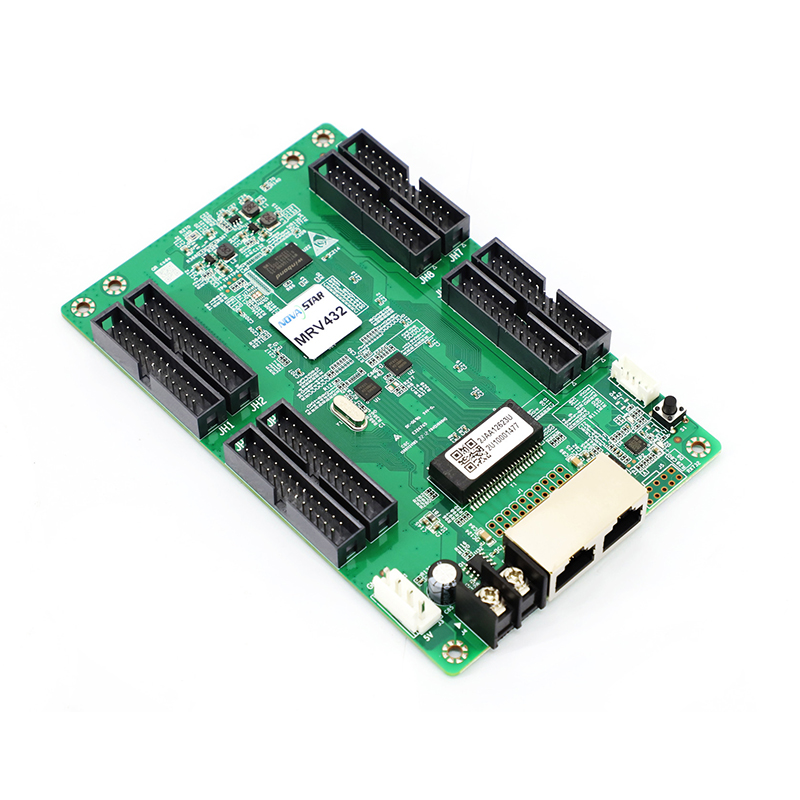
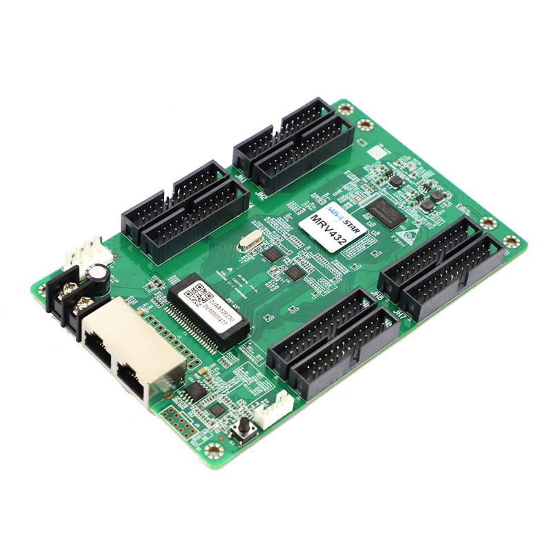
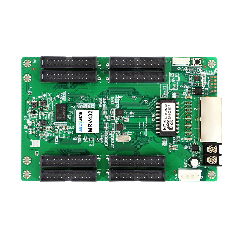
Novastar MRV432 Receiving Card With HUB320 Ports For Fine Pitch LED Screen
Introduction
The MRV432 is a general receiving card developed by NovaStar. A single MRV432 loads up to 512×512 pixels. Supporting various functions such as pixel level brightness and chroma calibration, quick adjustment of dark or bright lines, 3D, individual Gamma adjustment for RGB, and image rotation in 90° increments, the MRV432 can significantly improve the display effect and user experience.
The MRV432 uses 8 HUB320 connectors for communication. It supports up to 32 groups of parallel RGB data or 64 groups of serial data. Thanks to its EMC compliant hardware design, the MRV432 has improved electromagnetic compatibility and is suitable for various on-site setups.
Certifications
RoHS, EMC Class A
Features
Improvements to Display Effect
⬤Pixel level brightness and chroma calibration Work with the high-precision calibration system to perform brightness and chroma calibration on each LED to effectively remove brightness differences and chroma differences, enabling high brightness consistency and chroma consistency.
⬤Quick adjustment of dark or bright lines
The dark or bright lines caused by splicing of modules or cabinets can be adjusted to improve the visual experience. The adjustment can be easily made and takes effect immediately.
⬤3D function
Working with the sending card that supports 3D function, the receiving card supports 3D output.
⬤Individual Gamma adjustment for RGB Working with NovaLCT (V5.2.0 or later) and the sending card that supports this function, the receiving card supports individual adjustment of red Gamma, green Gamma and blue Gamma, which can effectively control image non- uniformity under low grayscale and white balance offset, allowing for a more realistic image.
⬤Image rotation in 90° increments
The display image can be set to rotate in multiples of 90° (0°/90°/180°/270°).
Improvements to Maintainability
⬤Mapping function
The cabinets can display the receiving card number and Ethernet port information, allowing users to easily obtain the locations and connection topology of receiving cards.
⬤Setting of a pre-stored image in receiving card The image displayed on the screen during startup, or displayed when the Ethernet cable is disconnected or there is no video signal can be customized.
⬤Temperature and voltage monitoring
The receiving card temperature and voltage can be monitored without using peripherals.
⬤Cabinet LCD
The LCD module of the cabinet can display the temperature, voltage, single run time and total run time of the receiving card.
⬤Bite error detection
The Ethernet port communication quality of the receiving card can be monitored and the number of erroneous packets can be recorded to help troubleshoot network communication problems.
NovaLCT V5.2.0 or later is required.
⬤Firmware program readback
The receiving card firmware program can be read back and saved to the local computer.
NovaLCT V5.2.0 or later is required.
⬤Configuration parameter readback
The receiving card configuration parameters can be read back and saved to the local computer.
Improvements to Reliability
⬤Loop backup
Appearance
The receiving card and sending card form a loop via the main and backup line connections. If a fault occurs at a location of the lines, the screen can still display the image normally.
⬤Dual backup of configuration parameters
The receiving card configuration parameters are stored in the application area and factory area of the receiving card at the same time. Users usually use the configuration parameters in the application area. If necessary, users can restore the configuration parameters in the factory area to the application area.
⬤Dual program backup
Two copies of firmware program are stored in the application area of the receiving card at the factory to avoid the problem that the receiving card may get stuck abnormally during program update.
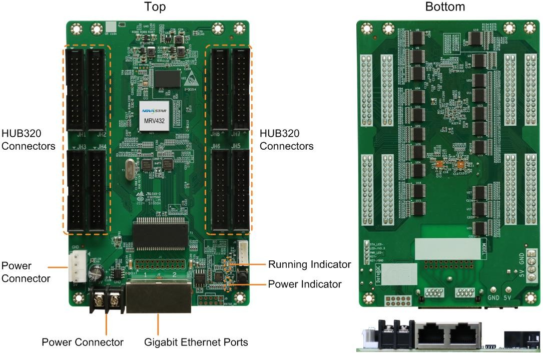
All product pictures shown in this document are for illustration purpose only. Actual product may vary.
Indicators
| Indicator | Color | Status | Description |
| Running indicator | Green | Flashing once every 1s | The receiving card is functioning normally. Ethernet cable connection is normal, and video source input is available. |
| Flashing once every 3s | Ethernet cable connection is abnormal. | ||
| Flashing 3 times every 0.5s | Ethernet cable connection is normal, but no video source input is available. | ||
| Flashing once every 0.2s | The receiving card failed to load the program in the application area and is now using the backup program. | ||
| Flashing 8 times every 0.5s | A redundancy switchover occurred on the Ethernet port and the loop backup has taken effect. | ||
| Power indicator | Red | Always on | The power input is normal. |
Indicators
| Name | Color | Status | Description |
| PWR | Red |
Staying on |
The power supply is working properly. |
| SYS | Green |
Flashing once every 2s |
The TB60 is functioning normally. |
|
Flashing once every second |
The TB60 is installing the upgrade package. | ||
|
Flashing once every 0.5s |
The TB60 is downloading data from the Internet or copying the upgrade package. | ||
| Staying on/off | The TB60 is abnormal. | ||
| CLOUD | Green | Staying on | The TB60 is connected to the Internet and theconnection is available. |
| Flashing once every 2s | The TB60 is connected to VNNOX and the connection is available. | ||
| RUN | Green | Flashing once every second | No video signal |
| Flashing once every 0.5s | The TB60 is functioning normally. | ||
| Staying on/off | FPGA loading is abnormal. |
Dimensions
The board thickness is not greater than 2.0 mm, and the total thickness (board thickness + thickness of components on the top and bottom sides) is not greater than 19.0 mm. Ground connection (GND) is enabled for mounting holes.
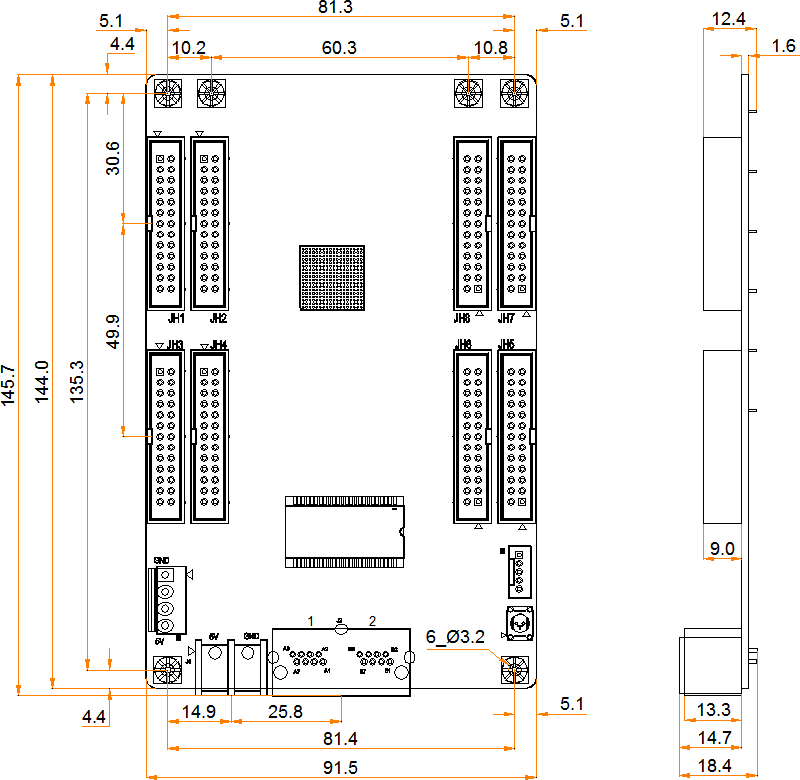
Tolerance: ±0.3 Unit: mm
Pins
32 Groups of Parallel RGB Data
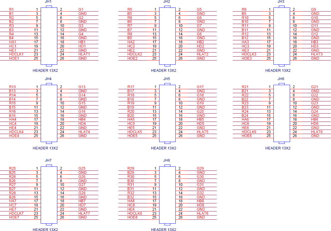
| JH1–JH8 | ||||||
| / | R | 1 | 2 | G | / | |
| / | B | 3 | 4 | GND | Ground | |
| / | R | 5 | 6 | G | / | |
| / | B | 7 | 8 | GND | Ground | |
| / | R | 9 | 10 | G | / | |
| / | B | 11 | 12 | GND | Ground | |
| / | R | 13 | 14 | G | / | |
| / | B | 15 | 16 | GND | Ground | |
| Line decoding signal | HA | 17 | 18 | HB | Line decoding signal | |
| Line decoding signal | HC | 19 | 20 | HD | Line decoding signal | |
| Line decoding signal | HE | 21 | 22 | GND | Ground | |
64 Grou
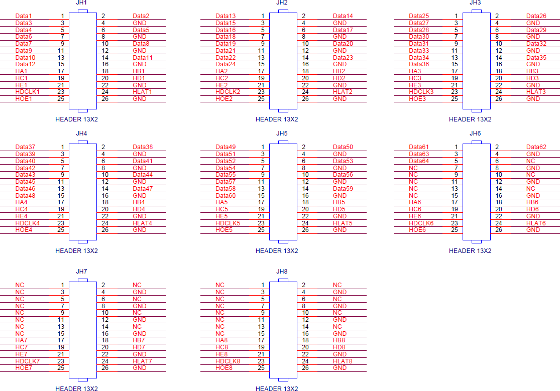
| JH1–JH5 | |||||
| / | Data | 1 | 2 | Data | / |
| / | Data | 3 | 4 | GND | Ground |
| / | Data | 5 | 6 | Data | / |
| / | Data | 7 | 8 | GND | Ground |
| / | Data | 9 | 10 | Data | / |
| / | Data | 11 | 12 | GND | Ground |
| / | Data | 13 | 14 | Data | / |
| / | Data | 15 | 16 | GND | Ground |
| Line decoding signal | HA | 17 | 18 | HB | Line decoding signal |
| Line decoding signal | HC | 19 | 20 | HD | Line decoding signal |
| Line decoding signal | HE | 21 | 22 | GND | Ground |
| Shift clock | HDCLK | 23 | 24 | HLAT | Latch signal |
| Display enable signal | HOE | 25 | 26 | GND | Ground |
| JH6 | |||||
| / | Data | 1 | 2 | Data | / |
| / | Data | 3 | 4 | GND | Ground |
| / | Data | 5 | 6 | NC | / |
| / | NC | 7 | 8 | GND | Ground |
| / | NC | 9 | 10 | NC | / |
| / | NC | 11 | 12 | GND | Ground |
| / | NC | 13 | 14 | NC | / |
| / | NC | 15 | 16 | GND | Ground |
| Line decoding signal | HA | 17 | 18 | HB | Line decoding signal |
| Line decoding signal | HC | 19 | 20 | HD | Line decoding signal |
| Line decoding signal | HE | 21 | 22 | GND | Ground |
| Shift clock | HDCLK | 23 | 24 | HLAT | Latch signal |
| Display enable signal | HOE | 25 | 26 | GND | Ground |
Specifications
| Maximum Resolution | 512×512@60Hz | |
| Electrical Specifications | Input voltage | DC 3.8 V to 5.5 V |
| Rated current | 0.5 A | |
| Rated power consumption | 2.5 W | |
| Operating Environment | Temperature | –20°C to +70°C |
| Humidity | 10% RH to 90% RH, non-condensing | |
| Storage Environment | Temperature | –25°C to +125°C |
| Humidity | 0% RH to 95% RH, non-condensing | |
| Physical Specifications | Dimensions | 145.7 mm × 91.5 mm × 18.4 mm |
| Net weight | 93.1 g
Note: It is the weight of a single receiving card only. |
|
| Packing Information | Packing specifications | Each receiving card is packaged in a blister pack. Each packing box contains 100 receiving cards. |
| Packing box dimensions | 625.0 mm × 180.0 mm × 470.0 mm | |
The amount of current and power consumption may vary depending on various factors such as product settings, usage, and environment.
Do you have any MOQ limit for led display order?
A: No MOQ, 1pc for sample checking is available.
What about the lead time?
A: Sample needs 15 days, mass production time needs 3-5 weeks depends on the quantities.
What is your after-sales service?
A: We can provide 100% guarantee for our products. If you have any questions, you will get our reply within 24 hours.
How about your Warranty Term?
A: Don’t worry, we have professional after-sale team to solve your any questions after you placed an order. And your exclusive sales engineer will also help you get over any problems.
How do you make our business long-term and good relationship?
A: 1. We keep good quality and competitive price to ensure our customers benefit ;
2. We respect every customer as our friend and we sincerely do business and make friends with them, no matter where they come from.
Products categories
-
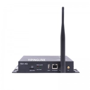
Novastar TB1-4G Multimedia Player Box TB1 For A...
-

Novastar VX400 Pro All in One Video Controller ...
-
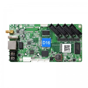
Huidu D16 Small LED Display Controller 640*64 P...
-

Huidu W62 Cost-effective LED Control Card with ...
-
Novastar MCTRL300 Nova LED Display Sending box
-

Huidu W3 Single Color Wi-Fi Control Card for Si...


