
Novastar MRV412 Receiving Card Nova LED Control System

Introduction
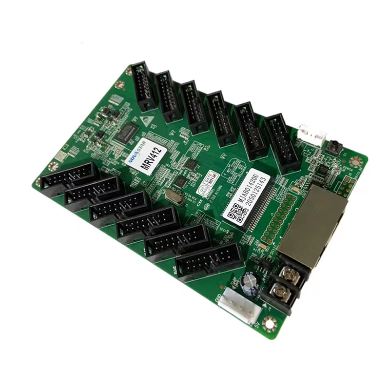
The MRV412 is a general receiving card developed by Xi’an NovaStar Tech Co., Ltd. (hereinafter referred to as NovaStar). A single MRV412 supports resolutions up to 512×512@60Hz (NovaL CT V5.3.1 or later required).
Supporting various functions such as color management, 18bit+, pixel level brightness and chroma calibration, individual gamma adjustment for RGB, and 3D, the MRV412 can significantly improve the display effect and user experience.
The MRV412 uses 12 standard HUB75E connectors for communication. It supports up to 24 groups of parallel RGB data. On-site setup, operation, and maintenance were all taken into account when designing the hardware and software of the MRV412, allowing for an easier setup, more stable operation, and more efficient maintenance.
Certifications
RoHS, EMC Class A
If the product does not have the relevant certifications required by the countries or regions where it is to be sold, please contact NovaStar to confirm or address the problem. Otherwise, the customer shall be responsible for the legal risks caused or NovaStar has the right to claim compensation.
Features
Improvements to Display Effect
⬤Color management
Allow users to freely switch the color gamut of the screen between different gamuts in real time to enable more precise colors on the screen.
⬤18bit+
Improve the LED display grayscale by 4 times to effectively deal with grayscale loss due to low brightness and allow for a smoother image.
⬤Pixel level brightness and chroma calibration Work with NovaStar’s high-precision calibration system to calibrate the brightness and chroma of each pixel, effectively removing brightness differences and chroma differences, and enabling high brightness consistency and chroma consistency.
⬤Quick adjustment of dark or bright lines
The dark or bright lines caused by splicing of modules or cabinets can be adjusted to improve the visual experience. The adjustment can be easily made and takes effect immediately.
⬤3D function
Working with the sending card that supports 3D function, the receiving card supports 3D output.
⬤Individual gamma adjustment for RGB
Working with NovaLCT (V5.2.0 or later) and the sending card that supports this function, the receiving card supports individual adjustment of red gamma, green gamma and blue gamma, which can effectively control image non- uniformity under low grayscale and white
Improvements to Maintainability
⬤Mapping function
The cabinets can display the receiving card number and Ethernet port information, allowing users to easily obtain the locations and connection topology of receiving cards.
⬤Setting of a pre-stored image in receiving card The image displayed on the screen during startup, or displayed when the Ethernet cable is disconnected or there is no video signal can be customized.
⬤Temperature and voltage monitoring
The receiving card temperature and voltage can be monitored without using peripherals.
⬤Cabinet LCD
The LCD module of the cabinet can display the temperature, voltage, single run time and total run time of the receiving card.
⬤Bite error detection
The Ethernet port communication quality of the receiving card can be monitored and the number of erroneous packets can be recorded to help troubleshoot network communication problems.
NovaLCT V5.2.0 or later is required.
⬤Firmware program readback
The receiving card firmware program can be read back and saved to the local computer.
NovaLCT V5.2.0 or later is required.
⬤Configuration parameter readback
The receiving card configuration parameters can be read back and saved to the local compute
Improvements to Reliability
⬤Loop backup
The receiving card and sending card form a loop via the main and backup line connections. If a fault occurs at a location of the lines, the screen can still display the image normally.
⬤Dual backup of configuration parameters
The receiving card configuration parameters are stored in the application area and factory area of the receiving card at the same time. Users usually use the configuration parameters in theapplication area. If necessary, users can restore the configuration parameters in the factory area to the application area.
⬤Dual program backup
Two copies of firmware program are stored in the application area of the receiving card at the factory to avoid the problem that the receiving card may get stuck abnormally during program update.
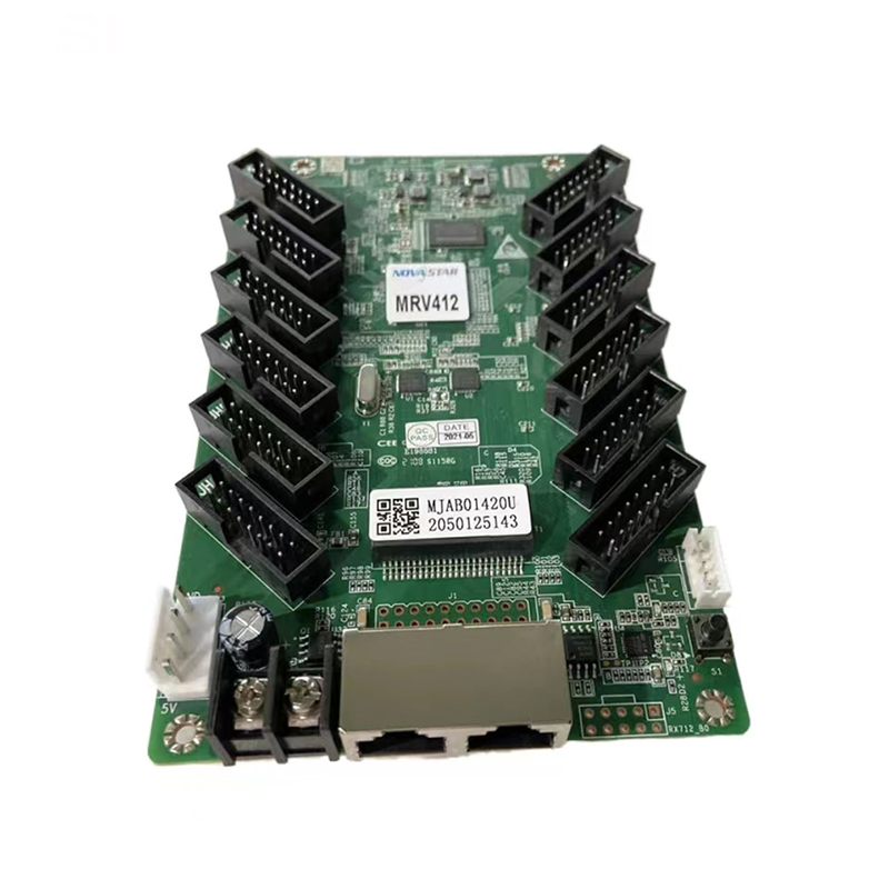
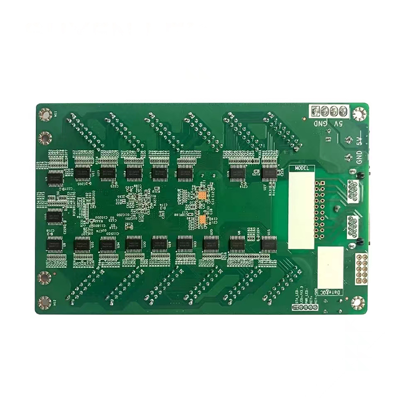
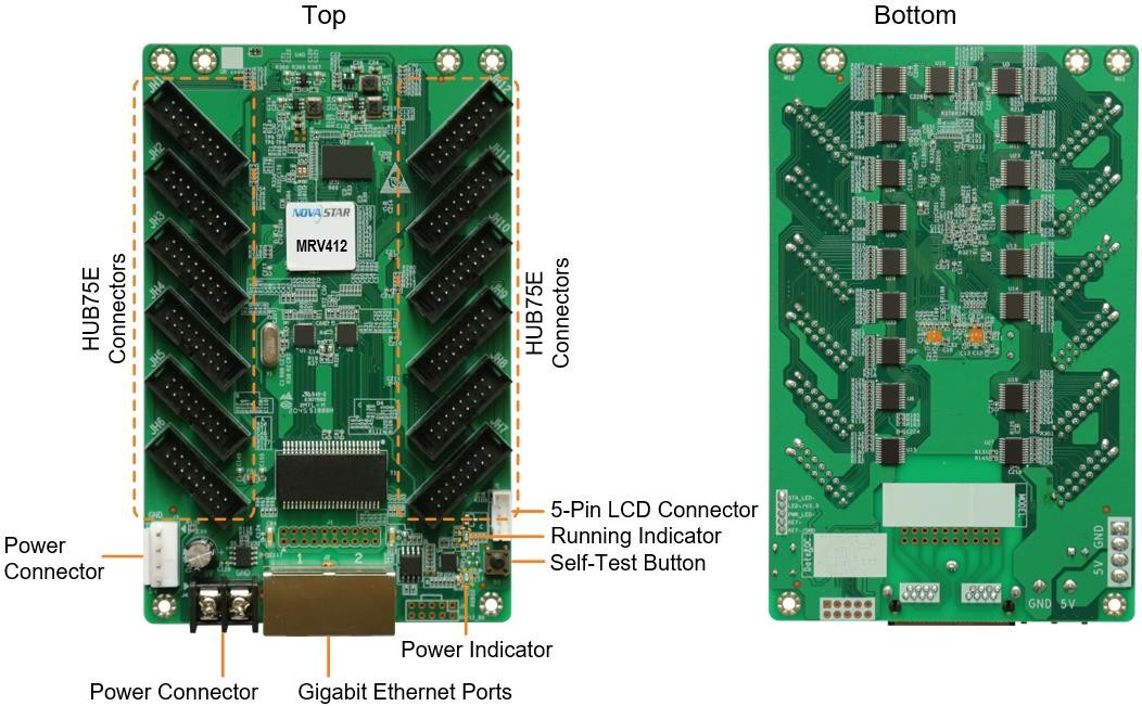
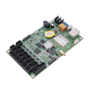
Appearance
All product pictures shown in this document are for illustration purpose only. Actual product may vary.
| Name | Description |
| HUB75E Connectors | Connect to the module. |
| Power Connector | Connect to the input power. Either of the connectors can be chosen. |
| Gigabit Ethernet Ports | Connect to the sending card, and cascade other receiving cards. Each connector can be used as input or output. |
| Self-Test Button | Set the test pattern.After the Ethernet cable is disconnected, press the button twice, and the test pattern will be displayed on the screen. Press the button again to switch the pattern. |
| 5-Pin LCD Connector | Connect to the LCD. |
Indicators
| Indicator | Color | Status | Description |
| Running indicator | Green | Flashing once every 1s | The receiving card is functioning normally. Ethernet cable connection is normal, and video source input is available. |
| Flashing once every 3s | Ethernet cable connection is abnormal. | ||
| Flashing 3 times every 0.5s | Ethernet cable connection is normal, but no video source input is available. | ||
| Flashing once every 0.2s | The receiving card failed to load the program in the application area and is now using the backup program. | ||
| Flashing 8 times every 0.5s | A redundancy switchover occurred on the Ethernet port and the loop backup has taken effect. | ||
| Power indicator | Red | Always on | The power input is normal. |
Dimensions
The board thickness is not greater than 2.0 mm, and the total thickness (board thickness + thickness of components on the top and bottom sides) is not greater than 19.0 mm. Ground connection (GND) is enabled for mounting holes.
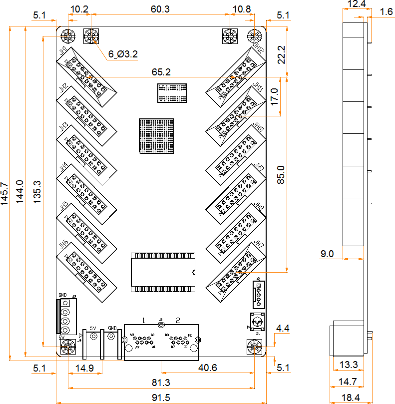
Tolerance: ±0.3 Unit: mm
To make molds or trepan mounting holes, please contact NovaStar for a higher-precision structural drawing.
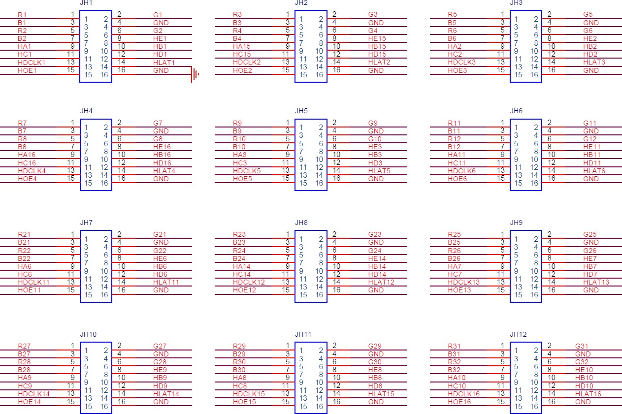
Pins
|
Pin Definitions (Take JH1 as an example) |
|||||
|
/ |
R1 |
1 |
2 |
G1 |
/ |
|
/ |
B1 |
3 |
4 |
GND |
Ground |
|
/ |
R2 |
5 |
6 |
G2 |
/ |
|
/ |
B2 |
7 |
8 |
HE1 |
Line decoding signal |
|
Line decoding signal |
HA1 |
9 |
10 |
HB1 |
Line decoding signal |
|
Line decoding signal |
HC1 |
11 |
12 |
HD1 |
Line decoding signal |
|
Shift clock |
HDCLK1 |
13 |
14 |
HLAT1 |
Latch signal |
|
Display enable signal |
HOE1 |
15 |
16 |
GND |
Ground |
Specifications
| Maximum Resolution | 512×512@60Hz | |
| Electrical Specifications | Input voltage | DC 3.8 V to 5.5 V |
| Rated current | 0.5 A | |
| Rated power consumption | 2.5 W | |
| Operating Environment | Temperature | –20°C to +70°C |
| Humidity | 10% RH to 90% RH, non-condensing | |
| Storage Environment | Temperature | –25°C to +125°C |
| Humidity | 0% RH to 95% RH, non-condensing | |
| Physical Specifications | Dimensions | 145.7 mm × 91.5 mm × 18.4 mm |
| Net weight | 93.1 g
Note: It is the weight of a single receiving card only. |
|
| Packing Information | Packing specifications | Each receiving card is packaged in a blister pack. Each packing box contains 100 receiving cards. |
| Packing box dimensions | 625.0 mm × 180.0 mm × 470.0 mm | |
The amount of current and power consumption may vary depending on various factors such as product settings, usage, and environment.
Products categories
-

Novastar TB10 Plus New Generation Multimedia Pl...
-
Novastar TCC70A Offline Controller Sender and R...
-

Huidu HDP601 Synchronous Single Window LED Vide...
-

Novastar TB30 Full Color LED Display Media Play...
-

Novastar CMS260 All-in-One Controller with 2.6 ...
-

Huidu 4K Video Processor VP1240A Support four-s...


