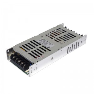
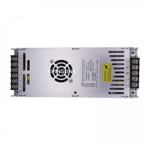
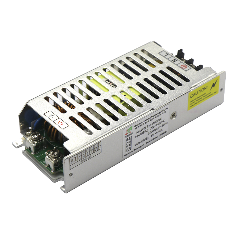
G-energy J200V5A1 Full Color LED Display Power Switch Supply
Product Main Specification
|
Output Power (W) |
Rated Input Voltage (Vac) |
Rated Output Voltage (Vdc) |
Output Current Range (A) |
Precision |
Ripple and Noise (mVp-p) |
|
200 |
180—264 |
+5.0 |
0-40.0 |
±2% |
≤200 |
Environment Condition
|
Item |
Description |
Tech Spec |
Unit |
Remark |
|
1 |
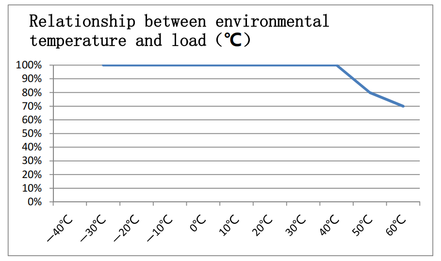
Working temperature |
-30—60 |
℃ |
Power supply housing temperature over 80 ℃ needs to increase heat dissipation area or reduce the amount of use |
|
2 |
Storing temperature |
-40—85 |
℃ |
|
|
3 |
Relative humidity |
10—90 |
% |
No condensation |
|
4 |
Heat dissipation method |
Natural cooling |
|
The power supply should be installed on the metal plate to dissipate heat |
|
5 |
Air pressure |
80— 106 |
Kpa |
|
|
6 |
Height of sea level |
2000 |
m |
Electrical Character
|
1 |
Input character | ||||
|
Item |
Description |
Tech Spec |
Unit |
Remark |
|
|
1.1 |
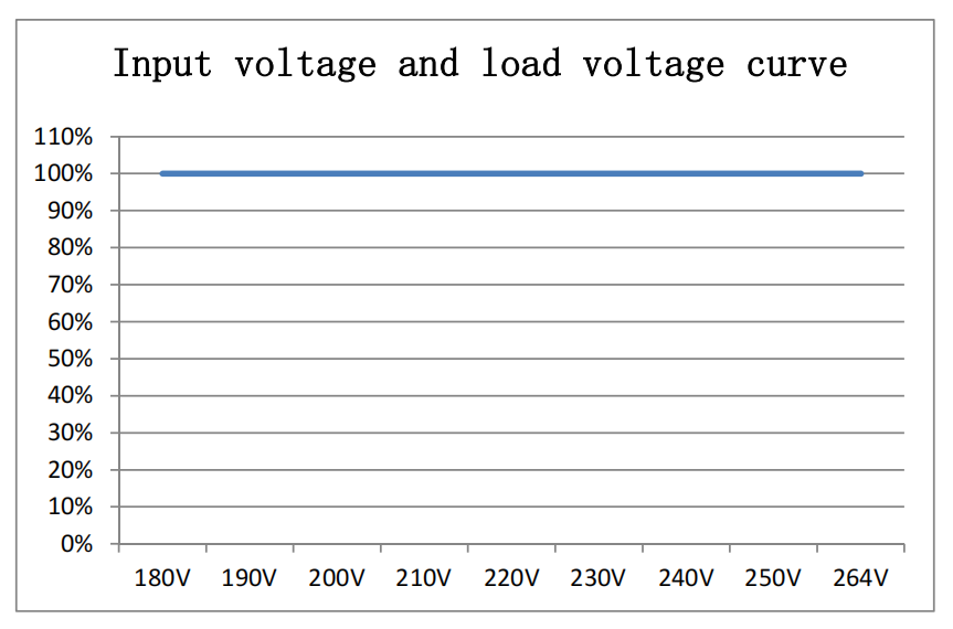
Rated voltage range |
200-240 |
Vac |
Refer to the diagram of input voltage and load relation. |
|
|
1.2 |
Input frequency range |
47—63 |
Hz |
|
|
|
1.3 |
Efficiency |
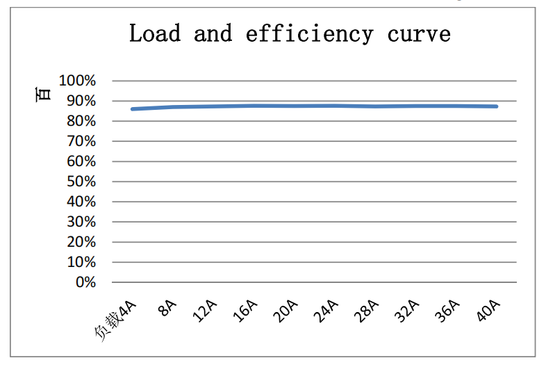
≥85.0 |
% |
Vin=220Vac 25℃ Output Full Load (at room temperature) |
|
|
1.4 |
Efficiency factor |
≥0.40 |
|
Vin=220Vac Rated input voltage, output full load |
|
|
1.5 |
Max input current |
≤3 |
A |
|
|
|
1.6 |
Dash current |
≤70 |
A |
@220Vac Cold state test @220Vac |
|
|
2 |
Output character | ||||
|
Item |
Description |
Tech Spec |
Unit |
Remark |
|
|
2.1 |
Output voltage rating |
+5.0 |
Vdc |
|
|
|
2.2 |
Output current range |
0-40.0 |
A |
|
|
|
2.3 |
Output voltage adjustable range |
4.2-5.1 |
Vdc |
|
|
|
2.4 |
Output voltage range |
±1 |
% |
|
|
|
2.5 |
Load regulation |
±1 |
% |
|
|
|
2.6 |
Voltage stability accuracy |
±2 |
% |
|
|
|
2.7 |
Output ripple and noise |
≤200 |
mVp-p |
Rated input, output full load, 20MHz bandwidth, load side and 47uf / 104 capacitor |
|
|
2.8 |
Start output delay |
≤3.0 |
S |
Vin=220Vac @25℃ test |
|
|
2.9 |
Output voltage raise time |
≤90 |
ms |
Vin=220Vac @25℃ test |
|
|
2.10 |
Switch machine overshoot |
±5 |
% |
Test conditions: full load, CR mode |
|
|
2.11 |
Output dynamic |
The voltage change is less than±10% VO; the dynamic response time is less than 250us |
mV |
LOAD 25%-50%-25% 50%-75%-50% |
|
|
3 |
Protection character | ||||
|
Item |
Description |
Tech Spec |
Unit |
Remark |
|
|
3.1 |
Input under-voltage protection |
135-165 |
VAC |
Test conditions: full load |
|
|
3.2 |
Input under-voltage recovery point |
140-170 |
VAC |
|
|
|
3.3 |
Output current limiting protection point |
46-60 |
A |
HI-CUP hiccups self-recovery, avoid long-term damage to power after a short-circuit power. |
|
|
3.4 |
Output short circuit protection |
Self-Recovery |
A |
||
|
3.5 |
over temperature protection |
/ |
|
|
|
|
4 |
Other character | ||||
|
Item |
Description |
Tech Spec |
unit |
Remark |
|
|
4.1 |
MTBF |
≥40,000 |
H |
|
|
|
4.2 |
Leakage Current |
<1(Vin=230Vac) |
mA |
GB8898-2001 test method |
|
Production Compliance Characteristics
|
Item |
Description |
Tech Spec |
Remark |
|
|
1 |
Electric Strength |
Input to output |
3000Vac/10mA/1min |
No arcing, no breakdown |
|
2 |
Electric Strength |
Input to ground |
1500Vac/10mA/1min |
No arcing, no breakdown |
|
3 |
Electric Strength |
Output to ground |
500Vac/10mA/1min |
No arcing, no breakdown |
Relative Data Curve
The mechanical character and the definition of connectors( unit:mm)
Dimensions: length× width× height=140×59×30±0.5.
Assembly Holes Dimensions
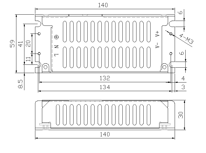
Above is the top view of the bottom shell. The specifications of the screws fixed in the customer system are M3, totaling 4. The length of the fixed screws entering the power supply body should not exceed 3.5mm.
Attention For Application
- Power supply to be safe insulation, any side of the metal shell with the outside should be more than 8mm safe distance. If less than 8mm need to pad 1mm thickness above PVC sheet to strengthen the insulation.
- Safe use, to avoid contact with the heat sink, resulting in electric shock.
- PCB board mounting hole stud diameter not exceeding 8mm.
Need a L355mm*W240mm*H3mm aluminum plate as auxiliary heat sink.