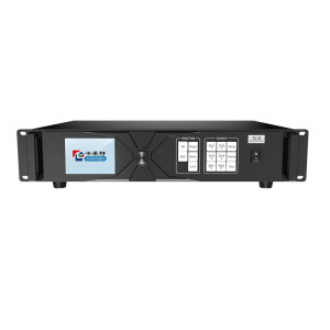
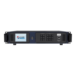
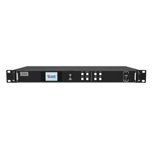
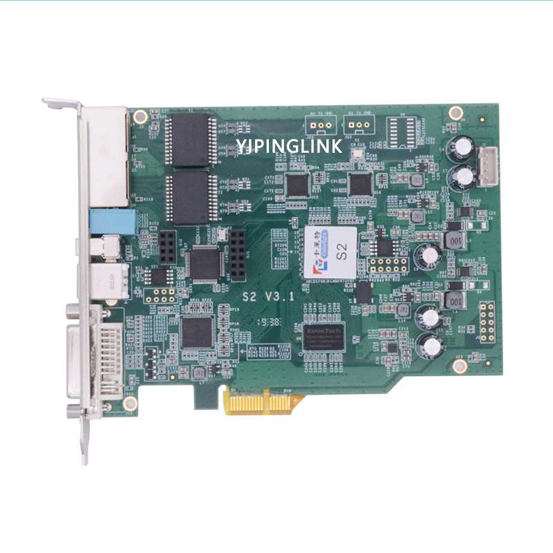
Colorlight sending card S2 sender work with 5A-75B 5A-75E for full color LED display video wall spairparts colorlight controller


Features
- DVI signal input port
- Audio input port with synchronous transmission via Ethernet cable
- Maximum input resolution: 1920×1200 pixels
- Loading capacity: 1.31 million pixels
- Maximum Width: 2560 pixels, Maximum Height: 2560 pixels
- 2 Gigabit Ethernet output ports support screen arbitrary splicing
- Dual USB ports for high speed configuration and easy cascading
- Improved grayscale performance at low brightness
- Wide working voltage with AC 100 ~ 240V
- Compatible with all series of Colorlight receiving cards
Specifications
| Video source interfaces | |
| Type | DVI |
| Receiving Resolution | 1920X1200 pixels |
| Frame Rate | Standard 60Hz, and auto adjustment |
| Gigabit Ethernet Outputs | |
| Quantity | 2 ports |
| Net Port Control Area | Each net port: 1280X512 pixels (or equivalent area) 2 net ports: 1280X1024 pixels (or equivalent area) Maximum width of single card: 2560 pixels
Or maximum height of single card: 2560 pixels |
| Transmission Distance | Recommended: CAT5e<100m |
| Net Port Splicing | Up-down or left-right splicing defined by users |
| Connecting Device | |
| Receiving Card | Compatible with all series of Colorlight receiving card |
| Peripherals | Multifunction cards, optical fiber transceiver, Gigabit switch |
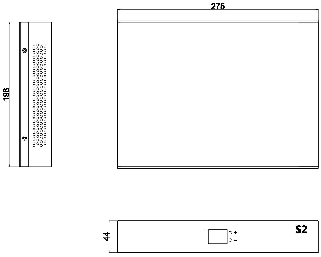
| Parameters | |
| Dimensions | 275X198X44 mm |
| Input Voltage | AC 100V-240V, 50/60HZ |
| Rated Power Consumption | 15W |
| Weight | 2.1kg |
| External Interface | |
| Configuration Port | USB |
| Real-time Configuration | Supported |
| Brightness and Color
Temperature Adjustment |
Supported |
| Smart Detection System | DVI interface detection |
| More Functions | |
| Multi-Screen Control | Multiple screens with different sizes can be controlled simultaneously |
| Audio Transmission | Supported |
| Bit Error Detection | Ethernet cable quality and malfunction detection |
Hardware
Interface Description
|
No |
Name |
Function |
Remarks |
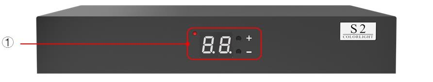
| 1 |
Indicator Panel and Configuration Button |
Adjust the brightness of the entire screen (16 levels); Display the whole screen test mode conversion | Press“+”and“-” together to switch between brightness adjustment and testing mode. |
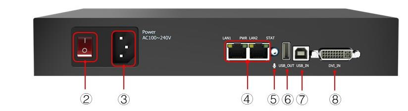
| 2 |
Power Switch |
On or off | |
| 3 |
Power Socket |
AC 100-240V | |
| 4 |
Output Ports |
RJ45, for transmitting network signals | The control area of the two outputs can be separately set |
| 5 |
Audio Input |
Input audio signal via Ethernet cable | |
| 6 |
USB OUT |
USB-A output, cascading among multiple sending cards | |
| 7 |
USB IN |
USB-B input, connected to PC for configuring parameters | |
| 8 |
DVI Input |
DVI output interface, connected to the graphics card |
Dimensions