
Colorlight 5A-75B LED Display Receiver Card


Functions and features
⬤Integrated 8-way HUB75 interface, more convenient with less cost
⬤Reduces the plug connectors and malfunction, lower failure rate
⬤Superior display quality: high refresh rate, high grayscale, and high brightness with the conventional chips
⬤Supports conventional chips, PWM chips, Silan chips
⬤Perfect performance under lower grayscale status
⬤Better detail processing: partial dark at row, reddish at low gray, shadow problems can be solved
⬤Supports high-precision pixel level calibration in the brightness and the chromaticity
⬤Supports up to 1/64 scan
⬤Supports any pumping point and any pumping row and pumping column and data group offset to realize various freeform display, spherical display, creative display, etc.
⬤Supports 16 groups of RGB signal parallel outputs
⬤Large loading capacity
⬤Wide working voltage range with DC3.8~5.5V
⬤Compatible with all series of Colorlighf s sending devices
Specifications
| Control System Parameters | |
| Control Area | Conventional: 128X512 pixels, PWM: 384X512 pixels |
| Network Port Exchange | Supported, arbitrary use |
| Synchronization | Nanosecond synchronization between cards |
| Display Module Compatibility | |
| Chip Supports | Supports conventional chips, PWM chips, Silan chips and other mainstream chips |
| Scan Type | Supports up to 1/64 scan |
| Module Specifications
Support |
Supports 8192 pixels within any row, any column |
| Cable Direction | Supports route from left to right, from right to left, from top to bottom, from bottom to top. |
| Data Group | 16 groups of RGB data |
| Data Folded | Supports 2 splits and 4 splits in the same direction, and 2 splits in the opposite direction |
| Data Exchange | 16 groups of data for any exchange |
| Module Pumping Point | Supported |
| Module Pumping Row,
Pumping Column |
Supported |
| Data Serial Transmission | Supports RGB, R16G16B16, etc. in the form of serial |
| Compatible Device and Interface Type | |
| Communication Distance | Suggest CAT5e cable W 100m |
| Compatible with
Transmission Equipment |
Gigabit switch, fiber converter, optical switches |
| DC Power Interface | Wafer VH3.96mm-4P, Barrier Terminal Block-8.25mm-2P |
| HUB Interface Type | HUB75 |
| Physical Parameters | |
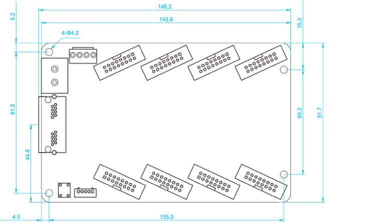
| Size | 145.2mmX91.7mm |
| Input Voltage | DC 3.8V-5.5V |
| Rated Current | 0.6A |
| Rated Power Consumption | 3W |
| Storage and Transport
Temperature |
-40°C~125°C |
| Operating Temperature | -25°C~75°C |
| Body Static Resistance | 2KV |
| Weight | 84g |
| Monitoring Functions (in conjunction with multi-function card) | |
| Monitoring Functions | Real time monitoring environment information like temperature, humidity and smoke |
| Remote Control | Supports for relay switch to turn on/off the power supply of equipment remotely |
| Other Features | |
| Pixel Level Calibration | Supported |
| Loop Backup | Supported |
| Shaped Screen | Supports various freeform display like spherical display, creative display, etc. through data group offset. |
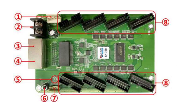
Hardware
|
S/N |
Name |
Function |
Remarks | |
|
1 |
Power 1 |
Connect DC 3.8 〜5.5V power supply for the receiving card |
Only one is used. | |
|
2 |
Power 2 |
Connect DC 3.8 〜5.5V power supply for the receiving card |
||
| 3 | Network port A |
RJ45, for transmitting data signals |
The dual network ports can achieve import/export at random, which can be identified in an intelligent way by the system. | |
|
4 |
Network port B |
RJ45, for transmitting data signals |
||
|
5 |
Power indicator light |
Red indicator light shows that the power supply is normal. |
DI | |
| Signal indicator light | Flashes once per second | Receiving card: normal working,
Network cable connection: normal |
D2 | |
| Flashes 10
times per second |
Receiving card: normal working,
Cabinet: Sorting & Highlight |
|||
| Flashes 4 times per second | Receiving card: backing up senders (loop backup status) | |||
|
6 |
Test button |
The attached test procedures can achieve four kinds of monochrome display (red, green, blue and white), as |
||
|
|
well as horizontal, vertical and other display scan modes. |
|||
|
7 |
External
interfaces |
For Indicator light and test button |
||
|
8 |
HUB pins |
HUB75 Interface, J1-J8 connected to display modules |
||
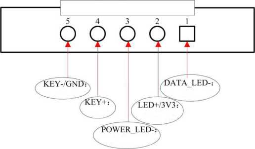
Definition of External Interface
Dimensions
Products categories
-

Colorlight X26m LED Video Processor Support 4K ...
-
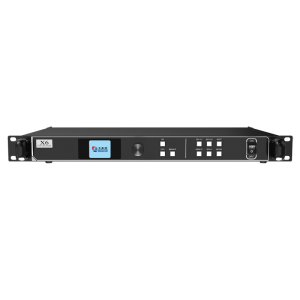
Colorlight X6 Video Processor Full Color LED Di...
-
Colorlight X8 Video Processor Full Color LED Di...
-

Colorlight VX20 LED Video Processor with 13.1 M...
-

Colorlight X40m 4K Video Processor with 40 Outp...
-

Colorlight A100 Support Sync and Async Modes LE...


